วันอาทิตย์ที่ 21 ตุลาคม พ.ศ. 2561

Microcontroller14

เครื่องตรวจจับโลหะ


อุปกรณ์

Arduino (any)Coil10nF capacitorBuzzerThe 1k resistor330-ohm resistorLED1N4148 diodeBreadboard or PCBConnecting jumper wire9v Battery

การต่อวงจร
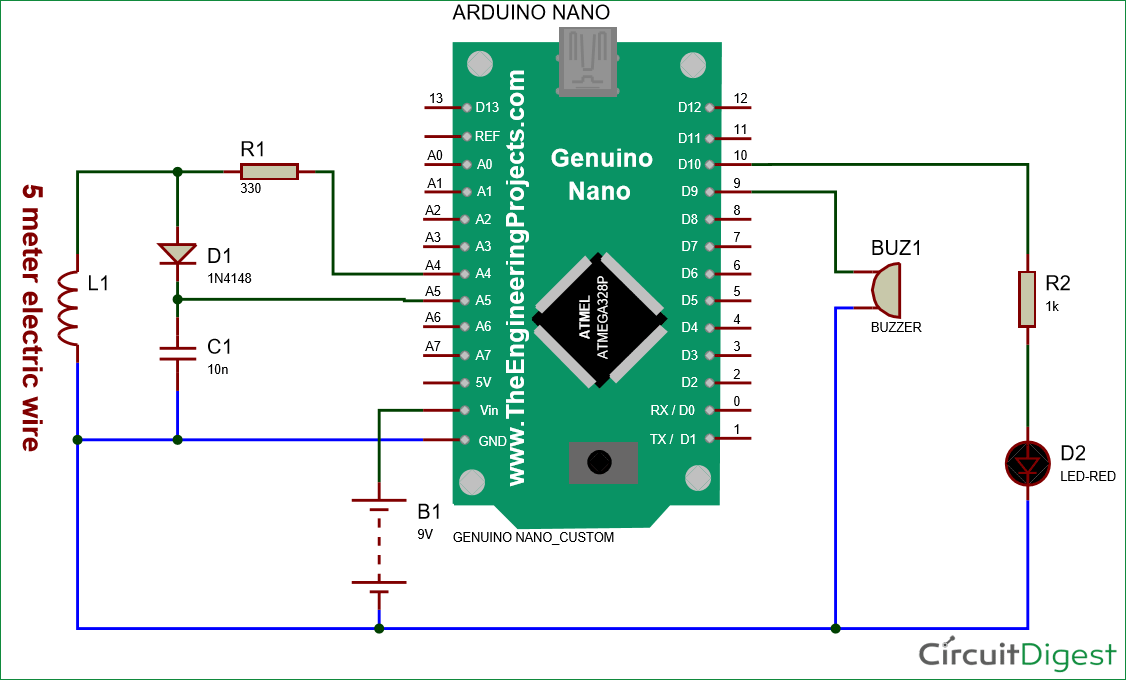


Dode

#define capPin A5
#define buz 9
#define pulsePin A4

#define led 10

long sumExpect=0; //running sum of 64 sums
long ignor=0;   //number of ignored sums
long diff=0;        //difference between sum and avgsum
long pTime=0;
long buzPeriod=0; 

void setup()
{
  Serial.begin(9600);
  pinMode(pulsePin, OUTPUT);
  digitalWrite(pulsePin, LOW);
  pinMode(capPin, INPUT); 
  pinMode(buz, OUTPUT);
  digitalWrite(buz, LOW);
  pinMode(led, OUTPUT);
}

void loop()
{
  int minval=1023;
  int maxval=0;
  long unsigned int sum=0;
  for (int i=0; i<256; i++)
  {
    //reset the capacitor
    pinMode(capPin,OUTPUT);
    digitalWrite(capPin,LOW);
    delayMicroseconds(20);
    pinMode(capPin,INPUT);
    applyPulses();
        //read the charge of capacitor

    int val = analogRead(capPin); //takes 13x8=104 microseconds
    minval = min(val,minval);
    maxval = max(val,maxval);
    sum+=val;
   
    long unsigned int cTime=millis();
    char buzState=0;
    if (cTime<pTime+10)
    {
      if (diff>0)
        buzState=1;
      else if(diff<0)
        buzState=2;
    }
    if (cTime>pTime+buzPeriod)
    {
      if (diff>0)
      buzState=1;
      else if (diff<0)
      buzState=2;
      pTime=cTime;  
    }
    if (buzPeriod>300)
    buzState=0;

    if (buzState==0)
    {
      digitalWrite(led, LOW);
      noTone(buz);
    } 
    else if (buzState==1)
    {
      tone(buz,2000);
      digitalWrite(led, HIGH);
    }
   
    else if (buzState==2)
    {
      tone(buz,500);
      digitalWrite(led, HIGH);
    }
  }

  //subtract minimum and maximum value to remove spikes
  sum-=minval;
  sum-=maxval;
 
  if (sumExpect==0)
  sumExpect=sum<<6; //set sumExpect to expected value
  long int avgsum=(sumExpect+32)>>6;
  diff=sum-avgsum;
  if (abs(diff)<avgsum>>10)
  {
    sumExpect=sumExpect+sum-avgsum;
    ignor=0;
  }
  else
    ignor++;
  if (ignor>64)
  {
    sumExpect=sum<<6;
    ignor=0;
  }
  if (diff==0)
    buzPeriod=1000000;
  else
  buzPeriod=avgsum/(2*abs(diff));   
}

void applyPulses()
{
    for (int i=0;i<3;i++)
    {
      digitalWrite(pulsePin,HIGH); //take 3.5 uS
      delayMicroseconds(3);
      digitalWrite(pulsePin,LOW);  //take 3.5 uS
      delayMicroseconds(3);
    }
}

Microcontroller13

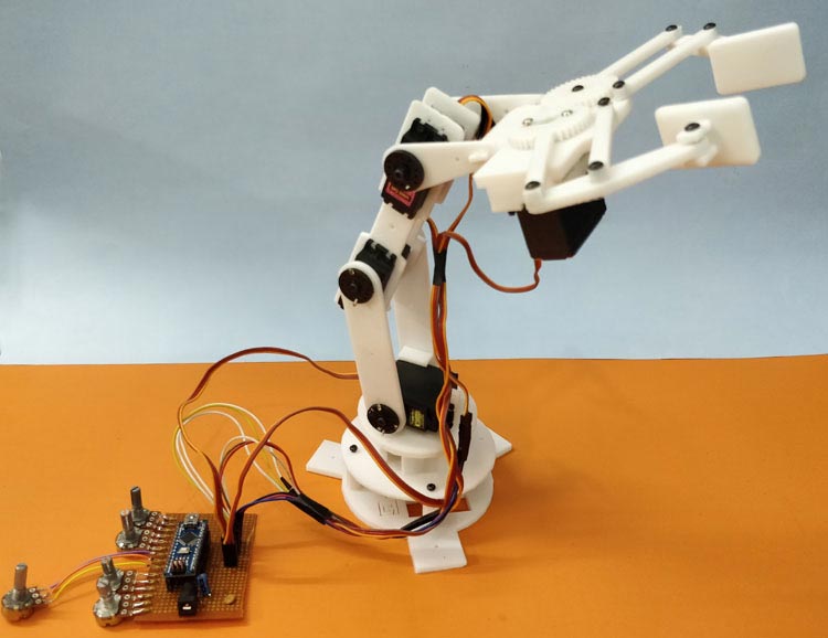
แขนกล

อุปกรณ์

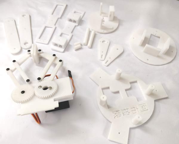
Arduino Nano5 MG-995 Servo Motor5-PotentiometerPerf BoardServo hornsNuts and Screws

การประกอบ


ต่อวงจร


Code

/*
   Robotic ARM with Record and Play option using Arduino
   Code by: B. Aswinth Raj
   Website: www.circuitdigest.com
   Dated: 05-08-2018
*/

#include <Servo.h> //Servo header file

//Declare object for 5 Servo Motors 
Servo Servo_0;
Servo Servo_1;
Servo Servo_2;
Servo Servo_3;
Servo Gripper;

//Global Variable Declaration
int S0_pos, S1_pos, S2_pos, S3_pos, G_pos;
int P_S0_pos, P_S1_pos, P_S2_pos, P_S3_pos, P_G_pos;
int C_S0_pos, C_S1_pos, C_S2_pos, C_S3_pos, C_G_pos;
int POT_0,POT_1,POT_2,POT_3,POT_4;

int saved_data[700]; //Array for saving recorded data

int array_index=0;
char incoming = 0;

int action_pos;
int action_servo;

void setup() {
Serial.begin(9600); //Serial Monitor for Debugging

//Declare the pins to which the Servo Motors are connected to
Servo_0.attach(3);
Servo_1.attach(5);
Servo_2.attach(6);
Servo_3.attach(9);
Gripper.attach(10);

//Write the servo motors to initial position
Servo_0.write(70);
Servo_1.write(100);
Servo_2.write(110);
Servo_3.write(10);
Gripper.write(10);

Serial.println("Press 'R' to Record and 'P' to play"); //Instruct the user
}

void Read_POT() //Function to read the Analog value form POT and map it to Servo value
{
   POT_0 = analogRead(A0); POT_1 = analogRead(A1); POT_2 = analogRead(A2); POT_3 = analogRead(A3); POT_4 = analogRead(A4); //Read the Analog values form all five POT
   S0_pos = map(POT_0,0,1024,10,170); //Map it for 1st Servo (Base motor)
   S1_pos = map(POT_1,0,1024,10,170); //Map it for 2nd Servo (Hip motor)
   S2_pos = map(POT_2,0,1024,10,170); //Map it for 3rd Servo (Shoulder motor)
   S3_pos = map(POT_3,0,1024,10,170); //Map it for 4th Servo (Neck motor)
   G_pos  = map(POT_4,0,1024,10,170);  //Map it for 5th Servo (Gripper motor)
}

void Record() //Function to Record the movements of the Robotic Arm
{
Read_POT(); //Read the POT values  for 1st time

//Save it in a variable to compare it later
   P_S0_pos = S0_pos;
   P_S1_pos = S1_pos;
   P_S2_pos = S2_pos;
   P_S3_pos = S3_pos;
   P_G_pos  = G_pos;
  
Read_POT(); //Read the POT value for 2nd time
 
   if (P_S0_pos == S0_pos) //If 1st and 2nd value are same
   {
    Servo_0.write(S0_pos); //Control the servo
   
    if (C_S0_pos != S0_pos) //If the POT has been turned
    {
      saved_data[array_index] = S0_pos + 0; //Save the new position to the array. Zero is added for zeroth motor (for understading purpose)
      array_index++; //Increase the array index
    }
   
    C_S0_pos = S0_pos; //Saved the previous value to check if the POT has been turned
   }

//Similarly repeat for all 5 servo Motors
   if (P_S1_pos == S1_pos)
   {
    Servo_1.write(S1_pos);
   
    if (C_S1_pos != S1_pos)
    {
      saved_data[array_index] = S1_pos + 1000; //1000 is added for 1st servo motor as differentiator
      array_index++;
    }
   
    C_S1_pos = S1_pos;
   }

 if (P_S2_pos == S2_pos)
   {
    Servo_2.write(S2_pos);
   
    if (C_S2_pos != S2_pos)
    {
      saved_data[array_index] = S2_pos + 2000; //2000 is added for 2nd servo motor as differentiator
      array_index++;
    }
   
    C_S2_pos = S2_pos;
   }

   if (P_S3_pos == S3_pos)
   {
    Servo_3.write(S3_pos);
   
    if (C_S3_pos != S3_pos)
    {
      saved_data[array_index] = S3_pos + 3000; //3000 is added for 3rd servo motor as differentiater
      array_index++;
    }
   
    C_S3_pos = S3_pos;  
   }

   if (P_G_pos == G_pos)
   {
    Gripper.write(G_pos);
   
    if (C_G_pos != G_pos)
    {
      saved_data[array_index] = G_pos + 4000; //4000 is added for 4th servo motor as differentiator
      array_index++;
    }
   
    C_G_pos = G_pos;
   }
  
  //Print the value for debugging
  Serial.print(S0_pos);  Serial.print("  "); Serial.print(S1_pos); Serial.print("  "); Serial.print(S2_pos); Serial.print("  "); Serial.print(S3_pos); Serial.print("  "); Serial.println(G_pos);
  Serial.print ("Index = "); Serial.println (array_index);
  delay(100);
}

void Play() //Functon to play the recorded movements on the Robotic ARM
{
  for (int Play_action=0; Play_action<array_index; Play_action++) //Navigate through every saved element in the array
  {
    action_servo = saved_data[Play_action] / 1000; //The fist character of the array element is split for knowing the servo number
    action_pos = saved_data[Play_action] % 1000; //The last three characters of the array element is split to know the servo postion 

    switch(action_servo){ //Check which servo motor should be controlled
      case 0: //If zeroth motor
        Servo_0.write(action_pos);
      break;

      case 1://If 1st motor
        Servo_1.write(action_pos);
      break;

      case 2://If 2nd motor
        Servo_2.write(action_pos);
      break;

      case 3://If 3rd motor
        Servo_3.write(action_pos);
      break;

      case 4://If 4th motor
        Gripper.write(action_pos);
      break;
    }

    delay(50);
   
  }
}

void loop() {

if (Serial.available() > 1) //If something is received from serial monitor
{
incoming = Serial.read();
if (incoming == 'R')
Serial.println("Robotic Arm Recording Started......");
if (incoming == 'P')
Serial.println("Playing Recorded sequence");
}

if (incoming == 'R') //If user has selected Record mode
Record();

if (incoming == 'P') //If user has selected Play Mode
Play();

}

Microcontroller12

Hardware


Sorfware

//define the input/output pins

//pump/relay pins

#define PUMP_1_PIN 7

#define PUMP_2_PIN 8

//pushbutton pins

#define BUTTON_1_PIN 2

#define BUTTON_2_PIN 4

//Time for pumping stations to turn on in milliseconds

#define PUMP_1_TIME 2500

#define PUMP_2_TIME 2500

//setup() runs once

void setup()

{

  //setup output pins for relays/pumping stations

  pinMode(PUMP_1_PIN, OUTPUT);

  pinMode(PUMP_2_PIN, OUTPUT);


  //setup input pins for buttons

  pinMode(BUTTON_1_PIN, INPUT);

  pinMode(BUTTON_2_PIN, INPUT);  

}

//loop() runs indefinitely

void loop()

{

  //check pushbutton on pin BUTTON_1_PIN to see if it is HIGH (it has been pressed)

  if(digitalRead(BUTTON_1_PIN) == HIGH)

  {

     digitalWrite(PUMP_1_PIN, HIGH); //turn pump 1 on

     delay(PUMP_1_TIME);             //wait PUMP_1_TIME milliseconds

     digitalWrite(PUMP_1_PIN, LOW);  //turn pump 1 off

  }


  //check pushbutton on pin BUTTON_2_PIN to see if it is HIGH (it has been pressed)

  if(digitalRead(BUTTON_2_PIN) == HIGH)

  {

     digitalWrite(PUMP_2_PIN, HIGH); //turn pump 2 on

     delay(PUMP_2_TIME);             //wait PUMP_2_TIME milliseconds

     digitalWrite(PUMP_2_PIN, LOW);  //turn pump 2 off

  }

}

Microcontroller11

โปรเจคหุ่นยนต์ Arduino UNO + L298P บังคับด้วย Bluetooth


โปรเจค นี้จะเป็นการนำ Arduino UNO R3 และ L298P Motor Shield Board มาทำเป็น หุ่นยนต์ บังคับด้วย สมาร์ทโฟน แอนดรอยด์ ผ่านทาง Bluetooth HC-06 ซึ่งการใช้ L298P Motor Shield จะทำให้การประกอบหุ่นยนต์ สะดวกและง่ายขึ้น เมื่อเทียบกับการใช้ Motor Driver Module L298N

อุปกรณ์ที่ใช้

1. 2WD Smart Car Robot Chassis Kits

2. Arduino UNO R3 - Made in italy

3. L298P Motor Shield Board

4. Jumper (M2M) cable 20cm Male to Male

5. แจ๊กขั้วถ่าน 9 โวลต์ สำหรับ Ardiuno

6. สกรูหัวกลม+น็อตตัวเมีย ยาว 12 มม.

7. รางถ่าน 18650 แบบ 2 ก้อน

8. ถ่านชาร์จ 18650 Panasonic NCR18650B 3.7v  จำนวน 2 ก้อน

9. Jumper (F2M) cable 20cm Female to Male

10. Bluetooth HC-06 Slave


1. ประกอบหุ่นยนต์

เริ่มต้นด้วยการ ประกอบ หุ่นยนต์ UNO + L298P และ ทดสอบการเคลื่อนที่ของหุ่นยนต์ ตามลิงค์ บทความด้านล่าง

https://robotsiam.blogspot.com/2017/12/uno-l298p.html


2. ประกอบ Bluetooth HC-06

ใช้ จั้มเปอร์ ผู้-เมีย เชื่อมต่อ Bluetooth HC-06 เข้ากับ L298P ตามรูปด้านล่าง

HC-06 <-> L298P

VCC <-> 5V
GND <-> Gnd
TXD <-> RX(0)
RXD <-> TX(1)


3. การอัพโหลดโปรแกรม

/*

    Bluetooth Robot with Arduino UNO + L298P
    For more details visit:
    https://robotsiam.blogspot.com/2017/12/uno-l298p-bluetooth.html

*/

#include <SoftwareSerial.h>

int incomingByte = 0;

/*-------definning Outputs------*/

int MA1 = 12;     // Motor A1
int MA2 =  3;     // Motor A2
int PWM_A =  10;   // Speed Motor A

int MB1 =  13;     // Motor B1
int MB2 =  8;     // Motor B2
int PWM_B =  11;  // Speed Motor B

int SPEED = 200;  // Speed PWM สามารถปรับความเร็วได้ถึง 0 - 255

void setup() {

  //Setup Channel A
  pinMode(12, OUTPUT); //Motor A1
  pinMode(3, OUTPUT); //Motor A2
  pinMode(10, OUTPUT); //Speed PWM Motor A

  //Setup Channel B
  pinMode(13, OUTPUT);  //Motor B1
  pinMode(8, OUTPUT);  //Motor B2
  pinMode(11, OUTPUT); //Speed PWM Motor B

  Serial.begin(9600);
  Serial.println("Motor Ready");

}

void loop() {

  if (Serial.available() > 0) {
    incomingByte = Serial.read();
  }

  switch (incomingByte)
  {
    case 'S':
      // stop all motors
      {
        Stop(1);
        Serial.println("Stop\n");
        incomingByte = '*';
      }

      break;

    case 'F':
      // turn it on going forward
      {
        Forward(1);
        Serial.println("Forward\n");
        incomingByte = '*';
      }
      break;

    case 'B':
      // turn it on going backward
      {
        Backward(1);
        Serial.println("Backward\n");
        incomingByte = '*';
      }
      break;

    case 'R':
      // turn right
      {
        turnRight(1);
        Serial.println("Rotate Right\n");
        incomingByte = '*';
      }
      break;

    case 'L':
      // turn left
      {
        turnLeft(1);
        Serial.println("Rotate Left\n");
        incomingByte = '*';
      }
      break;

  }
}

void Forward(int time)
{
  digitalWrite(MA1, LOW);
  digitalWrite(MA2, HIGH);
  analogWrite(PWM_A, SPEED);

  digitalWrite(MB1, HIGH);
  digitalWrite(MB2, LOW);
  analogWrite(PWM_B, SPEED);

  delay(time);
}

void Backward(int time)
{
  digitalWrite(MA1, HIGH);
  digitalWrite(MA2, LOW);
  analogWrite(PWM_A, SPEED);

  digitalWrite(MB1, LOW);
  digitalWrite(MB2, HIGH);
  analogWrite(PWM_B, SPEED);

  delay(time);
}

void turnLeft(int time)
{
  digitalWrite(MA1, HIGH);
  digitalWrite(MA2, LOW);
  analogWrite(PWM_A, SPEED);

  digitalWrite(MB1, LOW);
  digitalWrite(MB2, LOW);
  analogWrite(PWM_B, 0);

  delay(time);
}

void turnRight(int time)
{
  digitalWrite(MA1, LOW);
  digitalWrite(MA2, LOW);
  analogWrite(PWM_A, 0);

  digitalWrite(MB1, LOW);
  digitalWrite(MB2, HIGH);
  analogWrite(PWM_B, SPEED);

  delay(time);
}

void Stop(int time)
{
  digitalWrite(MA1, LOW);
  digitalWrite(MA2, LOW);
  analogWrite(PWM_A, 0);

  digitalWrite(MB1, LOW);
  digitalWrite(MB2, LOW);
  analogWrite(PWM_B, 0);

  delay(time);

}

Microcontroller10

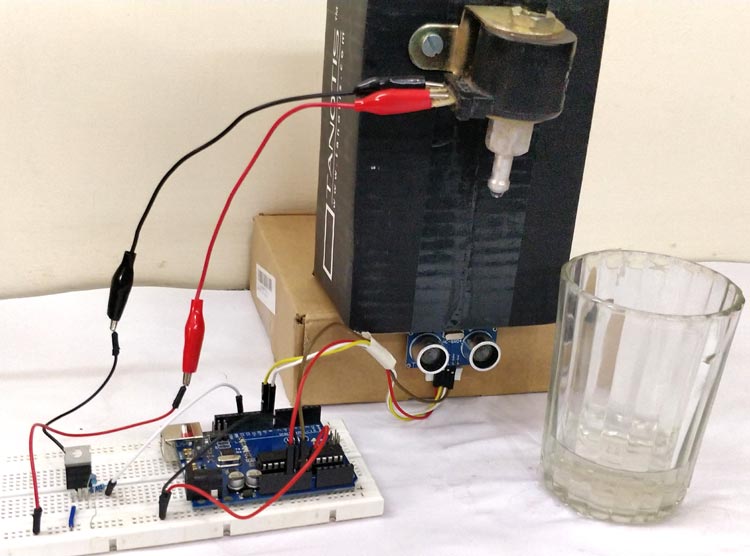
เครื่องเติมน้ำอัตโนมัติ


อุปกรณ์

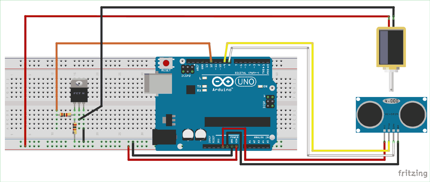
Solenoid ValveArduino Uno (any version)HCSR04 – Ultrasonic SensorIRF540 MOSFET1k and 10k ResistorBreadboardConnecting Wires

การต่อวงจร


Code

#define trigger 9
#define echo 8
#define LED 13
#define MOSFET 12


float time=0,distance=0;
 
void setup()
{
Serial.begin(9600);

 pinMode(trigger,OUTPUT);
 pinMode(echo,INPUT);
 pinMode(LED,OUTPUT);
 pinMode(MOSFET,OUTPUT);

 delay(2000);
}
 
void loop()
{
 measure_distance();

 if(distance<10)
 {
   digitalWrite(LED,HIGH);digitalWrite(MOSFET,HIGH);
 }
 else
 {
   digitalWrite(LED,LOW);digitalWrite(MOSFET,LOW);
 }

 delay(500);
}

void measure_distance()
{
 digitalWrite(trigger,LOW);
 delayMicroseconds(2);
 digitalWrite(trigger,HIGH);
 delayMicroseconds(10);
 digitalWrite(trigger,LOW);
 delayMicroseconds(2);
 time=pulseIn(echo,HIGH);
 
 distance=time*340/20000;
}

วันจันทร์ที่ 1 ตุลาคม พ.ศ. 2561

Mini Project

รดน้ำต้นไม้อัตโนมัติ
อุปกรณ์
                    1.เซนเซอร์วัดความชื่น
2.Relay1ตัว
      3.Arduino 1ตัว
4.ปั้มน้ำ 5V

Wiring diagram
Block
Code
#include <LiquidCrystal.h>
const int rs = 12, en = 11, d4 = 2, d5 = 3, d6 = 4, d7 = 5;
LiquidCrystal lcd(rs, en, d4, d5, d6, d7);

void setup() {

  Serial.begin(9600);
 lcd.begin(8, 2);
}

void loop() { 
  int sensorValue = analogRead(A0);
  Serial.println(sensorValue);
  delay(1);      
  if(sensorValue <= 300){
    analogWrite(A5, 255);
   lcd.setCursor(0,0);
   lcd.print("ON "); 
   
  }
  else{
    analogWrite(A5, 0);
    lcd.setCursor(0,0);
   lcd.print("OFF"); 
  }
}

วันอาทิตย์ที่ 30 กันยายน พ.ศ. 2561

งานแก้ไข แยก อธิบายส่วนต่างๆของproject


HARDWARE
1.Arduino uno r3
2.Bluetooth hc 06
3.2N2222
4.1N4007
5.Relay
6.Load
INPUT
1.Telephon
2.Bluetooth hc-06
MCU
1.Arduino UNO R3
OUTPUT
1.Relay
2.Load
SOFTWARE
#include <SoftwareSerial.h> นำข้อมูลจาก Linbrary SoftwareSerial มาใช้
const int rxPin = 4; ให้ขา 4 มีชื่อ rx
const int txPin = 2; ให้ขา 2 มีชื่อ tx
SoftwareSerial mySerial(rxPin, txPin); //ไว้ใช้กำหนดค่าลงใน ไลบรารี่ Bluetooth
const int Loads[] = {9, 10, 11, 12}; //ตัวแปรอาเรย์
int state = 0; //นี่คือตัวแปล state = 0
int flag = 0; ////นี่คือตัวแปล flag = 0
void setup() //เป็นฟังก์ชั่นแรกที่เมื่อ Arduino
{
for (int i=0;i<4;i++) //int=0<4และi+เรื่อยๆ
{
pinMode(Loads[i], OUTPUT); //สั่งกำหนดใช้ Load
}
Serial.begin(9600); ตั้งค่าSerial Monitor9600
for (int i=0;i<4;i++) ถ้าi=0และน้อยกว่า4ให้+เพิ่มไปเลยๆ
    {
   digitalWrite(Loads[i], LOW); สั่งให้ Loads เป็น LOW ถ้าเป็นหลอดไฟสั่งให้หลอดดับ
    }
}
void loop()
{

if(mySerial.available() > 0) //ถ้า mySerial.available() มากกว่า 0
{
state//คือการอ่านค่า = mySerial.read();
flag=0; //flag คือ 0
}
switch(state) //มันจะตรวจสอบว่าตัวแปรมีค่าเท่ากับ case ใด
{
case '0':digitalWrite(Loads[0], HIGH); //กำหนดcase 0 แสดงค่า Load อาเรย์ 0 ตั้งเป็น High
flag=1;              flag เท่ากับ 1
               break;                    หยุดการทำงาน
      case '1':digitalWrite(Loads[0], LOW);                case1 แสดงค่า Load อาเรย์ 0  เป็น Low
               flag=1;                    flag เท่ากับ 1
               break;                  หยุดการทำงาน
      case '2':digitalWrite(Loads[1], HIGH);              case2 แสดงค่า Load อาเรย์ 1  เป็น High
               flag=1;              flag เท่ากับ 1
               break;                หยุดการทำงาน
      case '3':digitalWrite(Loads[1], LOW);              case 3 แสดงค่า Load อาเรย์ 1  เป็น Low
               flag=1;                flag เท่ากับ 1
               break;                หยุดการทำงาน
      case '4':digitalWrite(Loads[2], HIGH);        case   4 แสดงค่า Load อาเรย์ 2  เป็น High
               flag=1;       flag เท่ากับ 1
               break;        หยุดการทำงาน
      case '5':digitalWrite(Loads[2], LOW);          case 5 แสดงค่า Load อาเรย์ 2  เป็น Low
               flag=1;         flag เท่ากับ 1
               break;         หยุดการทำงาน
      case '6':digitalWrite(Loads[3], HIGH);         case6 แสดงค่า Load อาเรย์ 3  เป็น High
               flag=1;        flag เท่ากับ 1
               break;       หยุดการทำงาน
      case '7':digitalWrite(Loads[3], LOW);        case7 แสดงค่า Load อาเรย์ 3  เป็น Low
               flag=1;     flag เท่ากับ 1
               break;      หยุดการทำงาน
      case '8':digitalWrite(Loads[0], LOW); case 8 แสดงค่า Load อาเรย์ 0  เป็น Low
               digitalWrite(Loads[1], LOW); แสดงค่า Load อาเรย์ 1 เป็น สถานะ Low
               digitalWrite(Loads[2], LOW); แสดงค่า Load อาเรย์ 2 เป็น สถานะ Low
               digitalWrite(Loads[3], LOW);  แสดงค่า Load อาเรย์ 3 เป็น สถานะ Low
               flag=1;             flag เท่ากับ 1
            break;                 
หยุดการทำงาน